Liquid Distributor
The distributor is a key element of the packed column and packing efficiency depends on good liquid distribution provided by the distributor.
LIQUID DISTRIBUTORS
The distributor is a key element of the packed column and packing efficiency depends on good liquid distribution provided by the distributor.
Distributors are installed above the packing beds in the columns and generally positioned at a distance between 50 and 250 mm above the packing bed. The space is defined by the design of the distributor and the vertical height required for disengaging the vapor phase of the packing before passing through the distributor gas passage area.
The multi-bed columns are complicated but some distillation process parameters as a high number of theoretical plates, the need for side draw product, or mixed liquid introduction into the column imposes a design of a multi-column bed and within this case a redistributor is necessary to create a uniform distribution of liquid over the bed of packing.
An ideal distributor has the following attributes
- Uniform liquid distribution
- Proper operation range
- Low vapor phase pressure drop
- Resistance to plugging
- Resistance to fouling
- Minimal liquid residence time
- Mixing capability for redistribution to the next bed
Liquid Distributor Test
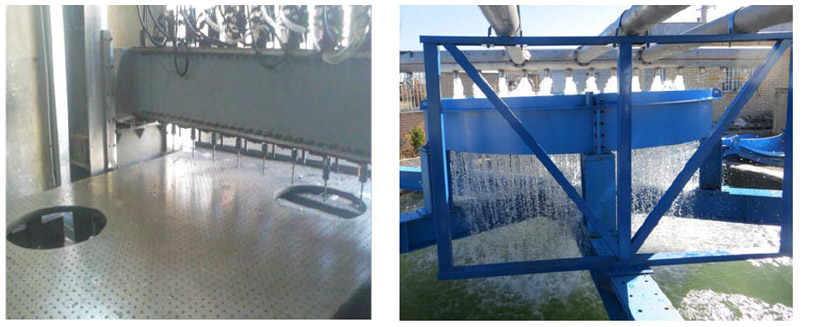
The distributor is a key element of the packed column and packing efficiency depends on good liquid distribution provided by the distributor. The packing performance is only possible with optimum distributor design. HMDS operates a test facility for liquid distributors to measure performance and demonstrate the quality of the distributors supplied.
Ability
Our facility can test liquid distributors Up to 10 meters
the discharged liquid flow is measured at various points below the liquid distributor.

Pan Distributor/Redistributor
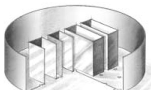
This device is provided with holes on the bottom surface and arranged so as to optimize the distribution and in such a way that risers placed between the holes allow the passage of gas. The distributor may not have risers
Deck Distributor /Redistributor Type
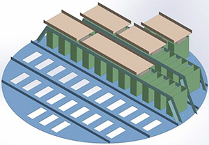
The distributor Model H1002 provides good liquid cross flow between orifices specifically spaced for optimum distribution. The distributor Model H1002 handles higher liquid flow rates. The orifices are large to avoid clogging. The standard turndown range is 2:1.
The control of feed velocity will be made by the feed pipe in case of single-phase liquid feeds to the distributor.
Through Distributor/Redistributor
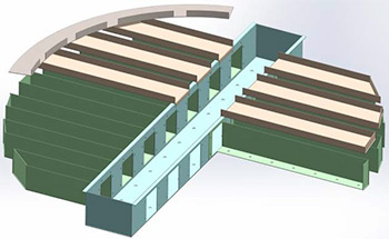
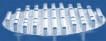
The through distributor Model H1005 with drip point is provided for a diameter above 300 mm with a liquid rate between 0.8 and 30 m3/m²/h. The orifices are located in sidewalls of the channels in order to take place in the lower vapor velocity region below the distributor.
Pan Distributor
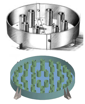
The holes are located on the distributor base and the gas passes through risers secured between the holes. For columns of diameter under 600 mm, the gas may pass between the distributor and the column wall.
The pan distributor Model H1007 is designed for columns between 250 and 1200 mm ID with a liquid rate between 2.5 and 20 m3/m²/h.
The pan distributor with V-Notch Risers is provided for high-fouling column.
Pipe Arm- Distributor
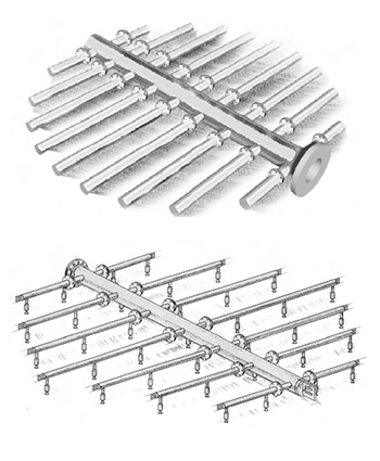
The distributor Model 1008 should be used only for clean service. When liquid contains solid particles, it is necessary to provide a filter to remove any particles that could clog the orifices due to its large open area that is used for high steam flow.
The distributor Model H1008 is a spray nozzle distributor with a liquid rate between 0.5 and 120 m3/m²/h. It is used where the complete vetting of packing bed is necessary and generally used in scrubbers, in the wash and circulating reflux.
Each spray covers the vital surface which allows the spray nozzle distributor to be designed for very low liquid rates.
Finned Distributor
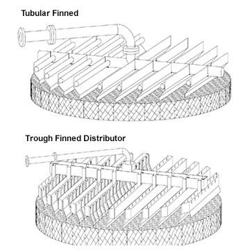
The use of a structured packing which enables improved efficiency imposes a dispenser for an optimum distribution of flow through the column.
EURO SLOT PARS distributor offers excellent capacity levels. HC-1009 is designed for columns equipped with a structured packing. HC-1009 distributor allows the liquid flow on the metal fins in the form of a thin continuous layer to the packing surface instead of drips in the case of a conventional distributor which might be drawn away by the gas flow to the above.
Mpdel HC-1009 dispenser benefits:
* The largest number of liquid irrigation points on the packing surface
* Maximum uniformity between the flow rates of the different points of liquid drainage
* High strength
* Operating flexibility
* Prevents drops and mist, which are driven by the gas flow
* Distribution without turbulence
* Large gas flow area to reduce the gas pressure drop and entrained liquid
* Easy installation
* Cost optimization
Trough Liquid Collector
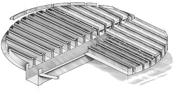
Model HC-1502 is used as long as the thermal expansion is a concern. The collector circumference rests on the support ring and is welded with a very thin weld bead to seal without a constrained expansion.
Chimney Tray Liquid Collector
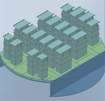
Vane Type Collector
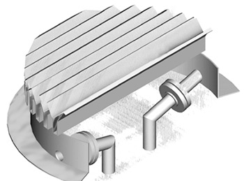
Its specific design allows for a high vapor capacity and a low pressure drop.
Feed Device
The performance of the tower is in close link with the quality of liquid and vapor entering in column and the choice of the feed tube which is generally classified into four categories:
- Liquid only
- Liquid and vapor above a packed bed
- Vapor only
- Reboiler returns
Liquid-Only Feed Pipe
The parameters that most influence the feed tube are distributor design & performance, flow rate, operating range, which is why the feed tube must be designed when the distributor design is completed.
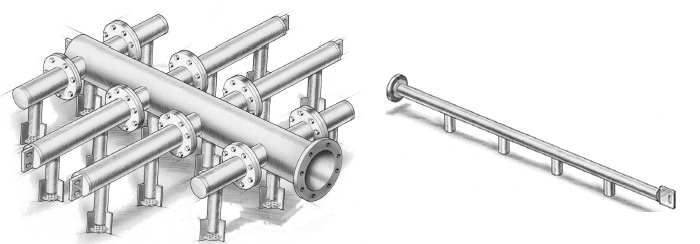
Flashing Feed Gallery, mixing phases
For a vapor/liquid mixture or flashing feed device above a distributor, the design of the feeding tube depends on the type of dispenser, liquid & gas flow rate, turndown, and column height required for vapor disengagement.
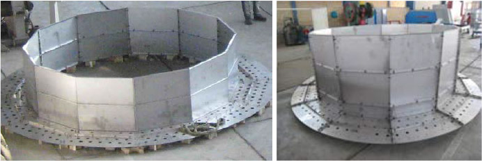
H-Vane Inlet Device
In the distillation column the inlet distributor should be designed properly because the large volume of gas causes poor distribution in the column if the distributor is not suitable. Poor distribution and high gas velocity causes the liquid re-entrainment.
It is therefore important to control the gas velocity by a properly designed distributor. The H-VID reduces the velocity of circulating gas and prevents re-entrainment of previously collected liquid. The H-VID reduces the dynamic of the inlet feed stream in a controlled manner and allows the removal of liquids, bulk solids and distributes the gas flow uniformly to the intended device.
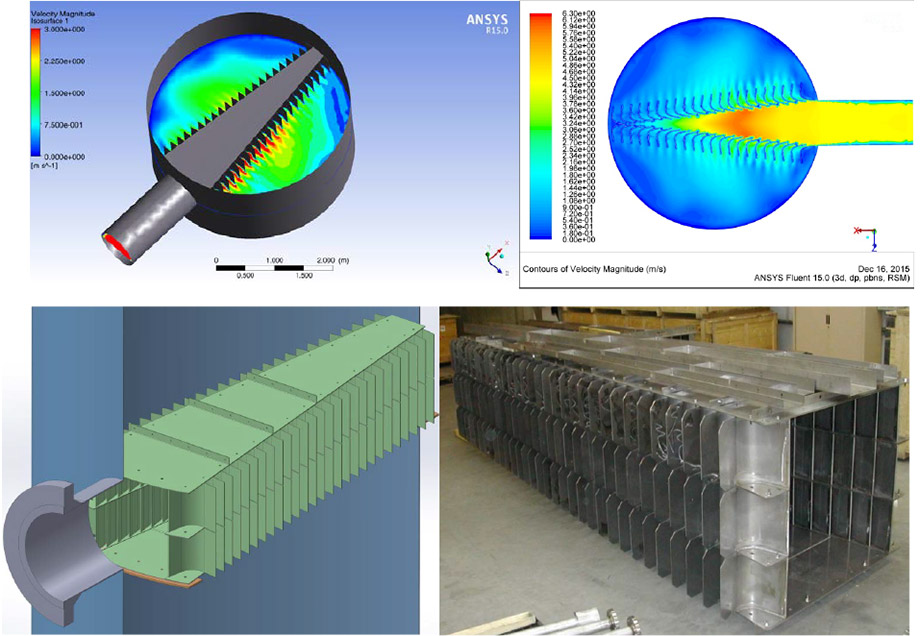
Vapor-Only Feeds
Two factors must be considered in the design of a vapor-only feed :
- The kinetic energy of the inlet vapor with respect to the packing bed pressure drop
- The recommended positioning of feed nozzle.
Vapor composition
When the vapor is introduced between packed beds, consider the degree of mixing of the inlet vapor with the rising vapor. If a gross mismatch of composition and/or temperature exists, mixing of both vapors optimizes packing performance above.
Specific equipment for vapor distribution may not be required if the pressure drop in the packed bed is sufficient for proper vapor distribution.
To determine the type of feed device required for a reboiler return, the first step is to consider the kinetic energy as described above. Once the required type of vapor distribution is determined, factors to consider include feed nozzle size and arrangement, pressure drop in the packed bed, flow rates, tower size and type of reboiler.
